Turbine rotors of gas and steam turbines can be greatly affected by stress, fatigue, corrosion, embrittlement, or cracking. All these factors can limit operational lifetime. Our lifetime assessment can maximize the life cycle of your rotor.
Maximize the operational lifetime of your turbine rotors
We offer:
A full range of maintenance services tailored to avoid complete failures or the destruction of your rotor
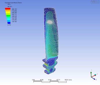
Engineering and technical services including lateral and torsional rotor dynamic analysis, finite element analysis, and modal analysis
Metallurgical analysis and testing services performed in our state-of the-art laboratories
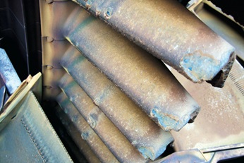
Hot corrosion damage in first-stage gas turbine blades
Limits to rotor lifetime
Until recently, turbine rotors were regarded as everlasting machines so long as no apparent damage was found. In recent years, a number of OEMs have stated that turbine rotors have a limited lifespan.
The following processes can limit the lifetime of turbine rotors, and even lead to complete destruction of the rotor:
External attack by corrosion or fretting
Stress corrosion cracking
Thermal fatigue
High cycle fatigue
Creep
Loss of ductility
Assessing rotor lifetime
Most industrial gas turbine manufacturers currently use Equivalent Operating Hours (EOH) as a basis for determining the remaining lifetime of gas turbine rotors.
The lifetime for a typical rotor is from 100,000 to 150,000 EOH. With a timely inspection of rotor parts, it is usually possible to achieve a single extension of about 50,000 to 100,000 EOH.
High temperature and high stress, either alone or in combination, can create lifetime-limiting effects. These effects can be calculated and checked, and the remaining lifetime can be assessed.
Lifetime-limiting processes progress slowly. Many processes are not directly related to EOH at all, unless a specific rate-of-attack is known and taken into account.
Possible causes of failure must be interpreted with care:
External attack by corrosion/fretting: This is determined by physical processes that can vary considerably. There is no fixed relation to EOH.
Stress corrosion cracking: This process depends on the corrosiveness of the environment, and it can vary considerably in gas turbines. There is no fixed relation to EOH.
Thermal fatigue: This process depends on the number of starts. Thermal fatigue alone has no fixed relation to EOH.
High cycle fatigue: There is no fixed relation to EOH.
Creep: Metal temperatures and stress levels are known and are more or less constant. There is a relation with OH (which could be approximated conservatively by EOH).
Loss of ductility: Metallurgical degradation is temperature- and time-dependent. Since rotor temperatures are stable in operation, there is a clear relation between progressive loss of ductility and EOH.
Low-alloy steel rotors have low metal temperatures (350°C to 400°C, or 600°F to 750°F). Therefore creep is not considered to be a major problem except in local areas with increased temperature and/or stress levels, such as fir tree serrations. Stress corrosion is only to be expected when very high static stress is present under a corrosive environment.
Loss of yield strength/stiffness and creep, however, are the only processes that could limit the lifetime of a rotor based on its EOH.
In order to extend rotor lifetime, you must carefully calculate both steady state (centrifugal) stress and dynamic (thermo-mechanical) stress levels. To calculate the effect of a defect on rotor lifetime, you will need both alloy toughness data and a fracture mechanical analysis so as to:
Determine the critical defect size for a stress rupture
Identify the defect growth rates of detected flaws
Calculate the number of cycles for defect growth to a safe fraction of the critical defect size
Verify findings with the expected operational time period
Alloy steels exhibit a transition from low ductility at low temperatures to much higher ductility at higher temperatures. This transition temperature, called the FATT (Fracture Appearance Transition Temperature), occurs after the appearance of the fracture of Charpy-V-notch test samples. The FATT in new materials is usually around 0°C to 120°C (32°F to 250°F). The alloy is brittle below the FATT; it is ductile above the FATT.
Temper embrittlement is a phenomenon in alloy steels created by the migration of specific trace elements (tin, antimony, phosphorus, arsenic) to the grain boundaries. Increased levels of these elements at the grain boundaries can shift the FATT to a higher temperature.
Neither the lower nor the upper platform ductility values are much affected by temper embrittlement; only the shift in the FATT extends the low ductility to a higher temperature.
Sensitivity to changes in the FATT is also determined by nickel and chromium, elements that are not the root cause of the shift. The presence of chromium and nickel increases this sensitivity significantly. By definition, nickel containing alloys do have good ductility. Their properties may change when exposed to high temperatures, however.
Consequences of temper embrittlement
When material properties (especially ductility and toughness) and operational stress levels are known, permissible defect sizes can be calculated.
There are two important criteria:
Critical defect size for unstable crack growth (fracturing) under given stress conditions
Minimal defect size for defect growth under given stress conditions (smaller defects will not grow and are safe)
Ideally parts should not contain defects larger than the minimum defect size for growth. Defect growth behavior can be determined when both the stress loading and the material behavior are known. In this case, a “safe-life” concept can be used to assess the significance of defects. “Safe-life” is used extensively in aeronautical engineering because of the sensitivity to fatigue, especially in aluminum alloys.
Gas turbine rotors are not designed with a “safe-life” concept. Thus defects are supposed to be below the minimum defect size for growth. In temper-embrittled material, the acceptance criteria for minimal and critical defect sizes are both reduced considerably.
Defect growth rates are not very dependent on the state of embrittlement.
Up to approx. 400°C (750°F), the defect growth rate increases only slightly when the material temperature increases.
Conditions for crack growth in rotors and disks are worse during the initial heating phase, e.g. at relatively low material temperatures. Therefore higher defect growth rates at higher temperatures are usually irrelevant.
Fracture mechanics use simplified models for cracks and other defects. Defects can have a wide variety of shapes and dimensions. They can also occur in clusters.
Most, if not all, inspection technologies only report “equivalent defect size” of detected indications. This means the indications look like defects with a standard shape and dimension. The real defect could therefore be either larger or smaller, or more or less dangerous.
Therefore it is highly recommended to use large safety factors for defect assessment after the initial lifetime assessment inspection. Once defects are detected, their potential growth or stability can be determined during future inspections. Follow-up inspections can use this information to reduce uncertainty about the significance of indications.
Ideally, the first inspection of a turbine rotor should take place at about 50% to 70% of the rotor’s specified lifetime. The inspection reports can be used as a reliable basis to assess the lifetime extension.